

BB Tool
CVD-Coated Carbide End Mill for Graphite & Composites | BK2060
CVD-Coated Carbide End Mill for Graphite & Composites | BK2060
受取状況を読み込めませんでした
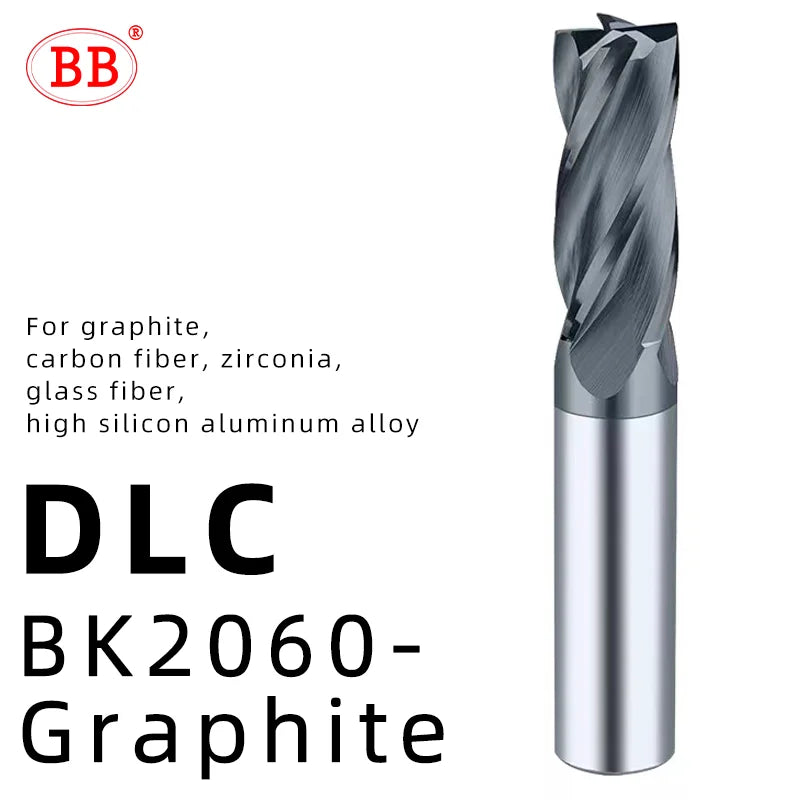
BK2060-Graphite
-CVD coated
-For graphite, carbon fiber, zirconia, glass fiber, high silicon aluminum alloy.


Finish Machining Composite
Optimized Flute Spacing for Stable Machining
DLC coating
Suitable Workpiece Materials:
Tempered glass, CFRP (Carbon Fiber Reinforced Plastic), GFRP (Glass Fiber Reinforced Plastic), glass / carbon fiber composites, and a wide range of non-metallic composite materials.
Suitable Machines:
CNC machining centers, CNC machine tools, engraving machines, precision engraving machines, high-speed machines, and more.


 Carbon Fiber CORE END MILL
2-flute fishtail,Flat Milling。
multi-flute corn-tooth,Cutting & Drilling。
2-flute fishtail cutting edge for clean surface finish, burr-free and fuzz-free cutting。
For CFRP / GFRP / wood / resin materials ect.
Large-Capacity Flutes Smooth Chip Evacuation


 CVD BK2060‑Graphite
Double-Arc Design:
Double-arc + 35° helix angle design for enhanced wear resistance — reduces burrs and delivers a superior surface finish.
U-Flute Design Efficient & Durable
For graphite,carbon fiber, zirconia,glass fiber,high silicon aluminum alloy
Extended Tool Life:More durable than standard tools Lower replacement costs
Stable Chatter-Free Cutting:Reduced Tool Breakage

 2F Ball Nose End Mill
Suitable Workpiece Materials:
Tempered glass, CFRP (Carbon Fiber Reinforced Plastic), GFRP (Glass Fiber Reinforced Plastic), glass / carbon fiber composites, and a wide range of non-metallic composite materials.
Sharp Cutting Edges
Fully Ground, Anti-Sticking
 Diamond-Coated Drills
Multi-Layer Coating, Extended Tool Life。
Efficient Tapping / More Holes, Faster Drilling。
Suitable Workpiece Materials:
Tempered glass, CFRP (Carbon Fiber Reinforced Plastic), GFRP (Glass Fiber Reinforced Plastic), glass / carbon fiber composites, and a wide range of non-metallic composite materials. · Reduce the spindle speed and feed rate when the effective length is long.
· Adjust the spindle speed and feed rate in proportion to the effective length relative to the tool diameter.
· The above cutting conditions are for reference only. Please adjust the parameters according to the actual workpiece geometry and machining purpose.
· If vibration or chatter occurs due to insufficient machine rigidity, adjust the spindle speed and feed rate from the values given in the table.
· Reduce the spindle speed and feed rate by 20% when the effective length is long.
· The bottom cutting edge is precision ground. When measuring the tool, use a non-contact measuring method to avoid damaging the cutting edge.
· The above cutting conditions are for reference only. Please adjust the parameters according to the actual workpiece geometry and machining purpose.
· If the listed spindle speed exceeds the maximum spindle speed of the machining center, or if burr formation occurs, adjust the spindle speed and feed rate appropriately.
· Air blow or coolant (cutting oil) is recommended. Pay attention to chip evacuation, heat generation, and risk of fire.

 · Reduce the spindle speed and feed rate by 20% when the effective length is long.
· The above cutting conditions are for reference only. Please adjust the parameters according to the actual workpiece geometry and machining purpose.
· If the listed spindle speed exceeds the maximum spindle speed of the machining center, or if burr formation occurs, adjust the spindle speed and feed rate appropriately.
· Air blow or coolant (cutting oil) is recommended. Pay attention to chip evacuation, heat generation, and risk of fire.
· Reduce the spindle speed and feed rate by 20% when the effective length is long.
· The bottom cutting edge is precision ground. When measuring the tool, use a non-contact measuring method to avoid damaging the cutting edge.
· The above cutting conditions are for reference only. Please adjust the parameters according to the actual workpiece geometry and machining purpose.
· If the listed spindle speed exceeds the maximum spindle speed of the machining center, or if burr formation occurs, adjust the spindle speed and feed rate appropriately.
· Air blow or coolant (cutting oil) is recommended. Pay attention to chip evacuation, heat generation, and risk of fire.

· The above cutting conditions are based on fz 0.03 mm/z and Vc 100 m/min. Please adjust the parameters according to the actual workpiece geometry and machining purpose.
· If the listed spindle speed exceeds the maximum spindle speed of the machining center, or if burr formation occurs, adjust the spindle speed and feed rate appropriately.
· Air blow or coolant (cutting oil) is recommended. Pay attention to chip evacuation, heat generation, and risk of fire.